Chasing after Volumetric Accuracy
Post Date: 15 Aug 2014 Viewed: 352
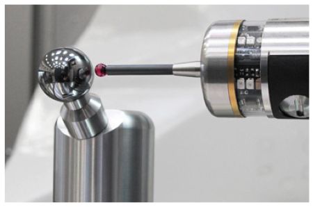
Chasing a precision sphere with a spindle probe as the sphere moves with the machine’s pallet throughout its five-axis machining range is the key to the new method.
One of the toughest challenges in five-axis machining of large parts is maintaining accuracy throughout the entire work zone. Ideally, a five-axis machine can produce results with the same accuracy when cutting in the far corners of the work zone or at its center. Grob Systems has developed a method of checking and compensating for possible distortions to a machine’s structure caused by the weight of a massive workpiece when machined in five axes.
Grob, a manufacturer of five-axis universal machines and production systems, says its new method improves accuracy of five-axis machines, especially those called upon to produce large, complex parts and components for critical applications. This is a summary of the company’s explanation of how this new system works:
The traditional approach to improving machine accuracy was to use laser interferometry to compensate the position accuracy of the individual axis, and the ball bar measurement to improve the perpendicularity between the axes. This is a simple technique and useful only for the three linear axes of the machine. When the spindle and table start moving around the work envelope, infinitely more deviations (both translational and rotary) come into play. That is the fundamental problem, and it becomes exponentially more complex when two additional rotational axes are introduced.
To improve the process for increasingly complex machines, Siemens pioneered the use of a six-dimensional pictorial compensation map. A 3D laser is used to simultaneously measure yaw and axis alignment, feeding data back to the machine’s control. The resulting picture is comprised of many, many points throughout the work zone. This created a much better measurement of geometry and positioning, allowing the CNC to compensate for distortion and improve volumetric accuracy anywhere in the work zone.
The limitation also of this approach is that the checks and compensation take place on the factory floor during final assembly, and it is available only for linear axes. In the real world, once you put a part on the pallet everything changes. Consider the capacity of some larger five-axis machines to accommodate loads up to 3,000 pounds. When a mass of that size is put into rotation on a five-axis machine, possibly suspended at 90 degrees, it creates a powerful force for distortion on any machine.
Simultaneous to the software developments at Siemens, Grob developed a function called Automatic Kinematics Adjustment. This process locates the true center of rotation, which is critical to accuracy in a five-axis work zone. It works like this: A spindle probe is paired with a precision sphere mounted on the pallet. A kinematic cycle touches probe to sphere, and then rotates to reposition the rotary axis. Repeat. Chasing the sphere around the five-axis envelope in this manner identifies the true center of rotation. The process takes about 10 minutes.
Grob has now integrated its kinematic process with the Siemens software to create what it calls the Volumetric Compensation System (VCS) for shop floor use. VCS applies the same basic software package used for Automatic Kinematic Adjustment, but takes it beyond the center of rotation. A probe stored in the tool magazine chases the sphere to map positional accuracy all around the work zone. By spinning and rotating the pallet, the probe identifies any rotational or translational deviation—from top to bottom of the Y stroke, maximum X to maximum Z and everything in between. The measured deviations are sent to the compensation software, which then perfects positioning accuracy. The process can applied to any critical component assigned to the Grob machine.


